There are tons of stereoscopic DVDs and VHS tapes on the market encoded as field interlaced stereo. Also, one of the easiest ways to make 3D video is with a camcorder (NTSC or PAL) and a NuView 3D adaptor (often selling on Ebay for less than $100.) For those of you who want to watch on a good old fashioned television, shutter glasses offer excellent 3D (but with some flicker.) Another use for NTSC/PAL shutter glasses is to preview on a field monitor when shooting 3D video.
3D glasses (wired) are a dime a dozen these days, but how do you synchronize them with the video fields of an NTSC or PAL TV signal. Today’s project shows you how to build and package a control circuit to do just that. It is simple and cheap, and the packaging is mighty rugged.
This fine example (pictured above) has endured about 7 years in the field shooting under all sorts of uncomfortable conditions. Its been to India, Thailand, Honduras, Mexico, Dominican Republic, and North St. Louis, to name a few.
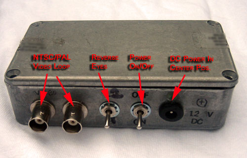
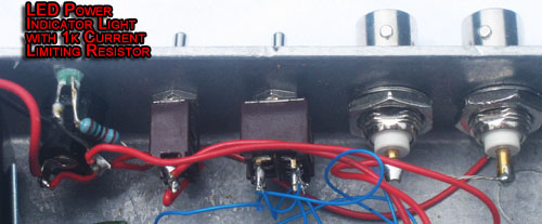
Looking at the connectors and controls from left to right:
- There’s 2 BNC connectors for video. They’re just a loop through. Plug your NTSC or PAL video source into either connector and your monitor into the other. The shutter control box will sense the video sync without altering the signal on the way to a color monitor.
- The first toggle switch lets us reverse which image goes to which eye. Sadly, there seems to be no standardization of field interleaved stereoscopic video with respect to which video field gets which eye’s view. This switch lets us put either field to either eye.
- The second switch turns the power on and off. In addition to an internal 9V battery, the control box can run off a 9-12 VDC wall wart or even a Anton-Bauer power pack.
- The jack on the right is for external DC power. There’s a small green LED above it to let us know when the control box is turned on.
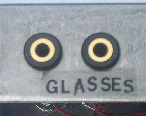
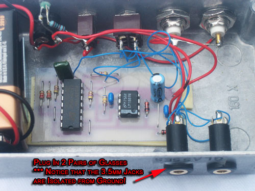
Connectors for 2 pairs of shutter glasses. Notice that they are isolated from ground (the metal box) by the black plastic sleeves.
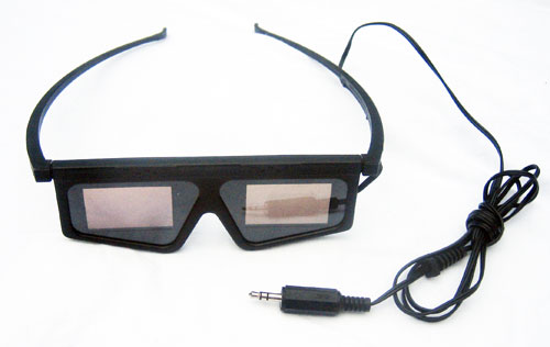
The control box will work with any brand of shutter glasses with a 3.5mm stereo mini plug such as the glasses shown below.
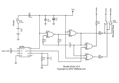
So… let’s get to the actual circuit. Fortunately it is quite simple; just 2 chips and a few other components. The metal case and toggle switches are the most expensive part of this project, but don’t worry, it isn’t much.
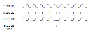
A quick description: Video comes in on the left through a coupling capacitor (C4) into an LM1881 sync separator chip. One of the outputs of this IC is an ODD/EVEN signal – binary logic for video field 1 or video field 2. Toward the right a CMOS 4030 quad exclusive-or chip is configured as a fast square wave generator. The frequency isn’t overly important, 500 hz to 1 khz is fine. The shutters on the glasses are made opaque by this square wave. The ODD/EVEN signal modulates this square wave flipping the shutters on and off. Opposing signals are generated for left and right eyes. A DPDT switch reverses the connections to the 2 shutters in the glasses.
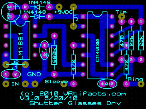
The first few of these that I built were hand wired on perf board, but eventually I moved over to a printed circuit board. You can download the layout as a PDF. For short runs you can use Press n’ Peel Blue to make the board. In order to keep this a one-sided PCB, there’s 2 jumpers: J1 and J2. Don’t forget to install them.
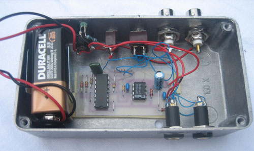
The hardest part of the project is manufacturing the enclosure, mounting the parts and wiring everything up. Its just time consuming. I used a Hammond 1590B metal box which is virtually indestructible. You’ll need to drill holes for all the jacks and connectors. Measure each connector carefully. Aluminum is soft and you can drill all the holes with a small hand drill. Drill everything before starting to mount and wire things. Brush out all the metal shavings before starting with the components.
The PCB is just tacked down with double sticky-sided tape (the thick foamy type.)
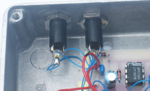
You MUST keep the sleeve of the 3.5 mm shutter jacks insulated from the metal case. If you’re using a plastic case, you can use any old stereo jack, but with a metal case you’ll need special ones like these (above.)
Wiring up the switches, BNC connectors, and power jack is straightforward. Just follow the schematic. You can substitute panel mounted RCA jacks if you don’t like BNC.
I used kynar (wire-wrap wire) for all the signals and 24 gauge stranded for all the power.
The battery holder clip is held in with a 4/40 screw, nut, and lockwasher.
Parts Sources
- LM1881 or EL1881 Sync Separator
- 4030 Quad Input Exclusive-OR
- On/Off Switch
- Reverse Eyes Switch
- 1N4148 Diodes
- 3.5mm Insulated Stereo Panel Jack
- Hammond 1590B
- Power Entry Connector – Panel Mount
- Battery Clip
- Battery Connector
- BNC Panel Jacks
- Resistors can be 1% 1/8 watt metal film
- Electrolytic capacitors can be 25V or greater with radial leads
- Other capacitors can be 25V or greater with radial leads

