Not long ago I needed a whole bunch of head trackers for just one week. Not wanting to invest tens of thousands of dollars in high-end tracking systems, I came up with an easy DIY head tracking system constructed from the guts of a Gyration Air Mouse. The Air Mouse contains a 2 degree of freedom (2 DOF – Yaw and Elevation) orientation sensor. In my application, users didn’t really roll their head (i.e. tilt their head from side to side), so 2 DOF actually worked pretty well. The tracker is really responsive with very little lag. I used Gyration’s Go Pro Air Mouse, but I suspect any of their Air Mouse family can be made to work. This article presents the hardware modification in detail and source code to integrate the tracker into your own software.
A quick disclaimer… The resulting head tracker will exhibit some drift over time. Its not perfect. However for short gaming sessions or experimental use, it is great. Also there are some good methods, explained at the end of this article, to minimize the drift.
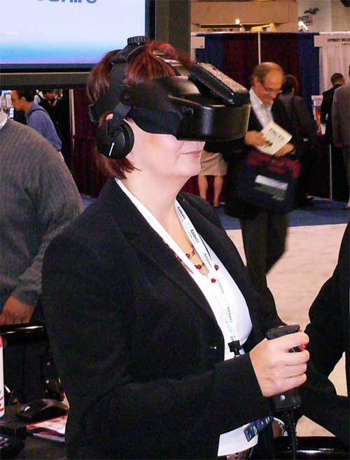
Head Tracker in Action on a V6 HMD
Step 1 – Tear out the guts of the mouse.
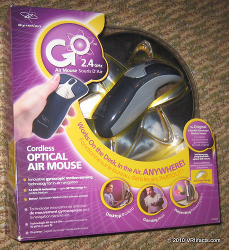
Start with a Gyration Cordless Optical Air Mouse
The Air Mouse is way too heavy to put on your head. Fortunately most of the weight is in the case and battery back, neither of which is needed. The actual circuit boards weigh less than an ounce, perfect for head attire.
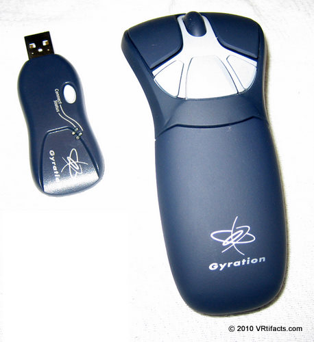
Just Keep These 2 Pieces: the Receiver and the Mouse
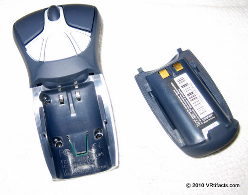
Remove the Battery. Its not needed.
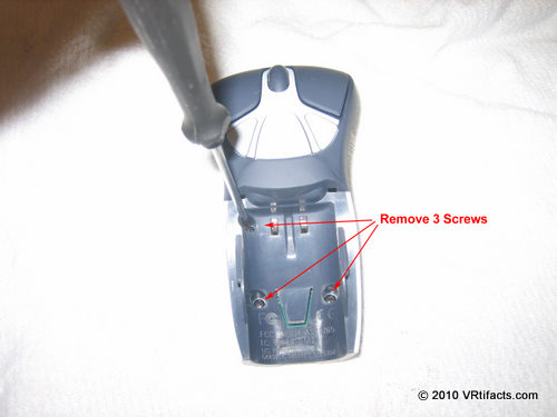
To open the mouse case, first remove these 3 screws.
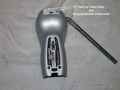
Then peel up the 2 teflon pads on the bottom front of the mouse and remove the 2 screws under the pads.
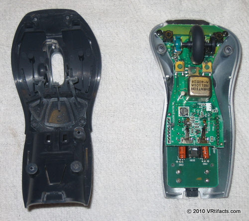
The mouse case will come apart. Discard the dark plastic piece on the left of this photo.
Step 2 – Extract the Circuit Boards
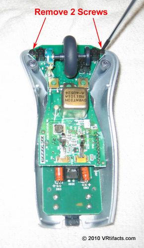
To free the circuit boards, remove these 2 screws.
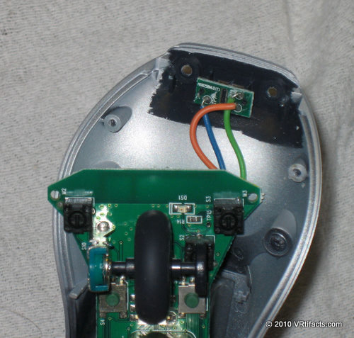
Pull the circuit boards free. The tiny board at the tip of the mouse is lightly glued on. Pull it off the plastic bottom of the mouse.
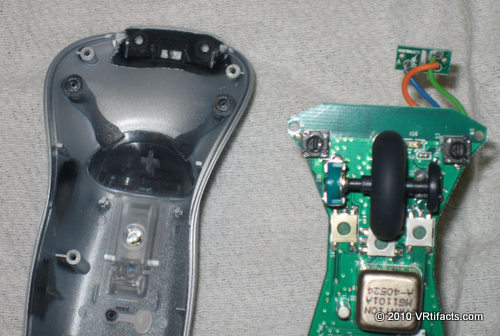
Discard the silver plastic mouse bottom shown on the left of this photo.
Step 3 – Remove the unnecessary junk from the circuit boards
There’s a bunch of stuff that just adds weight and size that we won’t be using. You’ll need a decent soldering iron, an X-acto knife, and either a solder sucker or solder removal braid.
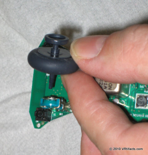
Pull the mouse wheel free and discard it.
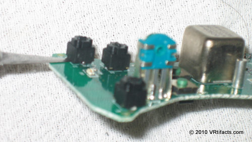
This is what’s left to work with.
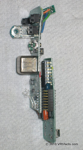
Side View
Separate the Big Board (with silver cube) from the little board.
Step 4 – Remove more junk…
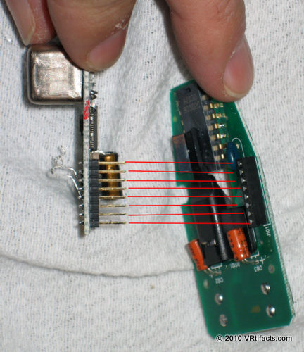
Unsolder 3 wires (Orange, Green, and Blue) from big board. These are the 3 wires that connect to the tiny board. Discard tiny board and attached wires.
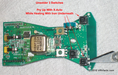
Unsolder these 3 black switches by prying from the top and unsoldering one side, then the other from the bottom.
Pry up switch while unsoldering from other side.
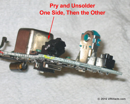
Here’s a switch with one side unsoldered. Just pull the other side free while unsoldering it. These are normal mouse buttons. You could keep them, or remote the switches elsewhere.
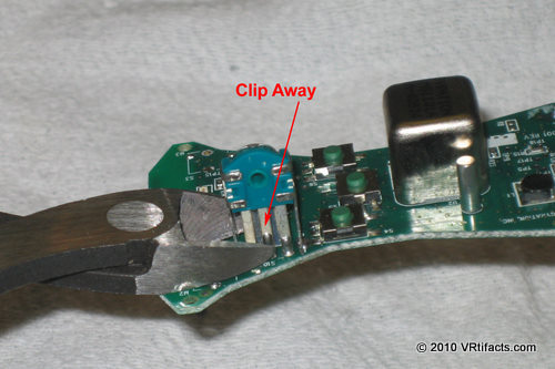
Clip away the encoder for the mouse wheel. Its hard to unsolder. I remove it to reduce weight and size of the final tracker.
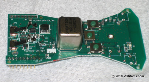
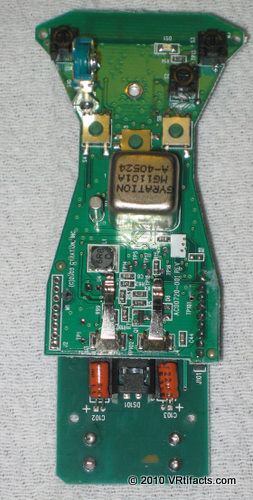
This is what’s left of the big board after removing the switches and encoder. You could remove the remaining 3 switches, but they’re difficult to unsolder and don’t weigh much anyway.
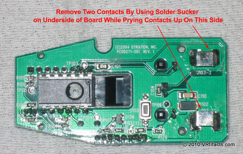
Step 5 – Remove the power connectors and bypass Air-mode switch
The battery contacts are a nuisance and might short themselves out later on. We’ll remove them. Also the Air Mouse has an inconvenient 2D/3D switch. We’ll bypass it so that the tracker is always in 3D Air Mode, not 2D Mouse Mode.
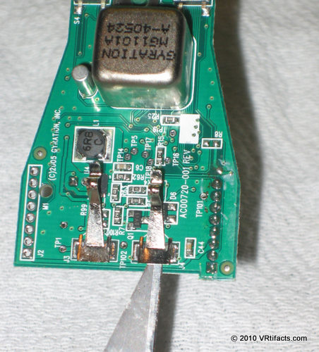
Remove the battery contacts by prying and unsoldering one side, then the other.
You’ll need to bend up the electrolytic capacitor at the bottom left in order to unsolder the contact underneath. Bend the cap flat to it’s original position when you’re done.
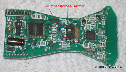
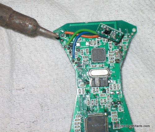
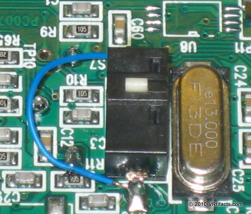
Solder a jumper across the Air Mouse switch. Wirewrap wire works well. The tracker should always be in 3D “Air” mode.
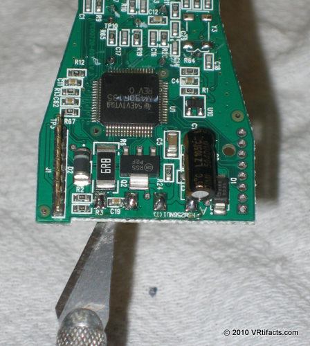
Head over to the little circuit board. Remove the battery charger contacts by using a solder sucker to remove excess solder, then prying each side up while heating with a soldering iron.
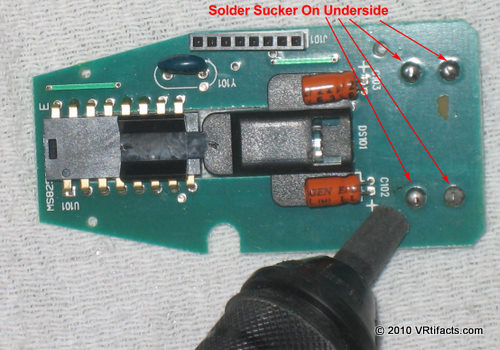
Solder sucker on underside of battery clips.
Step 6 – Trim some extra circuit board away to make it smaller.
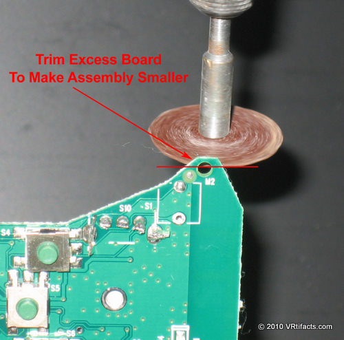
Make the big board a little smaller by trimming the mounting tabs with a Dremel cutoff wheel.
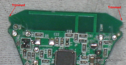
Notice the “F” shaped PCB trace at the top. That’s the 2.4 ghz antenna. Don’t cut it away.
Step 7 – Setup the new power source.
I chose to keep my head tracker as a “wired” device, the wire being a 3 VDC power cable. However, you can choose to make it wireless at the expense of some extra battery weight.
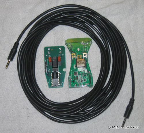
Power cord. I like soft flexible 3.5mm stereo audio cable. Any 2 conductor cable will work. The Gyration draws less that 15 ma at 3 volts DC. Since this is a self contained wireless device, you could make it battery powered at the expense of additional weight. Three AA alkaline batteries start at 4.5 volts and would last about 100 hours until they discharged down to 3 volts. A CR2450 lithium coin battery would last 15-20 hours of continuous use.
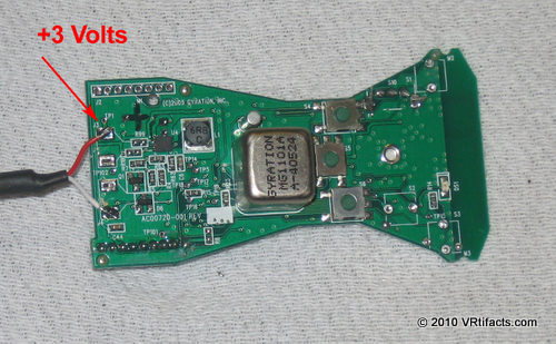
Connect Positive and Negative to the big board.
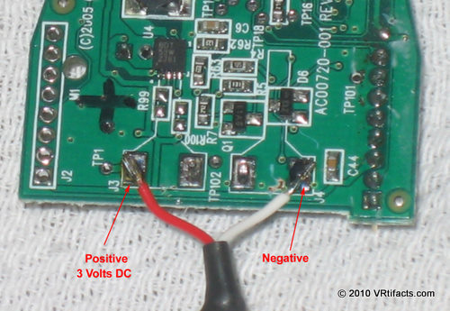
Detail of the power connections. 3 to 4 volts DC will work. I mark the positive side on the PCB with a felt tip pen.
Step 8 – Reassemble the boards.
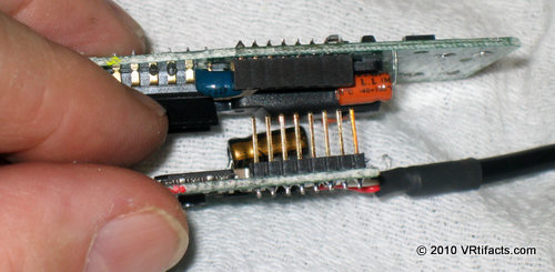
Put the 2 boards back together.
The boards are done!
Step 9 – Hooking up the head tracker
Its time to connect everything and fire it up!
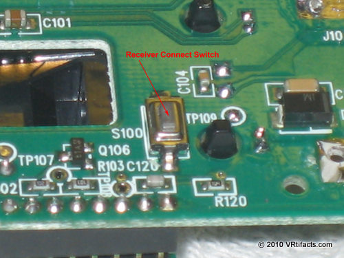
This is the push button switch to automatically choose channels to match the receiver. Its on the underside of the small board. The Gyration manual tells you how to sync the transmitter and receiver. Do it once and its done forever!
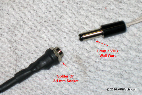
Solder on a 2.1 mm power socket on the other end of the 2 conductor cable. Be careful to put positive on the tip and negative on the sleeve.
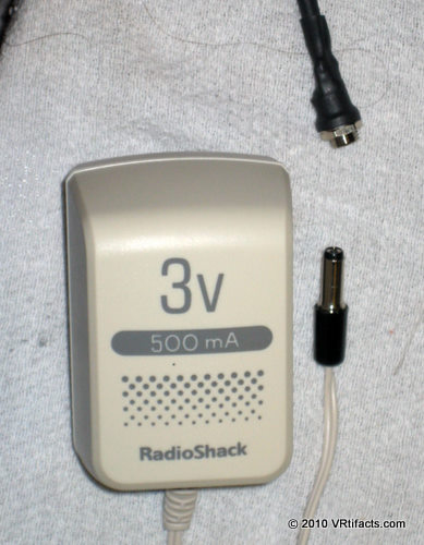
A Radio Shack 3 VDC 500 ma supply works well. The connector should be CENTER positive.
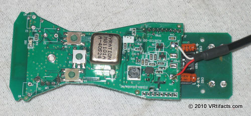
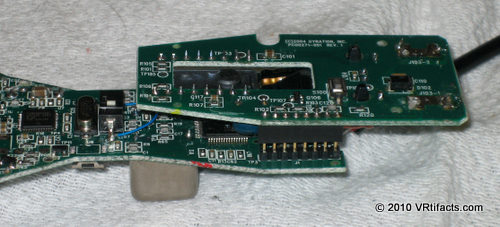
The completed tracker board assembly. Don’t forget to strain relief the power cord when you put this assembly in an enclosure. The component at the upper left labeled “DS1” is an activity LED. Whenever you move the tracker, this green LED will light in synchronization with the green Status LED on the USB receiver.
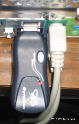
The Gyration receiver connected to a USB port on the back of the computer. Don’t install the Gyration software CD. Just let Windows install it’s own driver.
Step 10 – Packaging
I made a little thermo-form enclosure out of thin textured styrene. The cube is positioned bottom down. Rather than make the enclosure thicker, I chose to have the cube stick out the bottom, inasmuch as the velcro I used to secure the tracker to the helmet matches the protruding height of the cube.
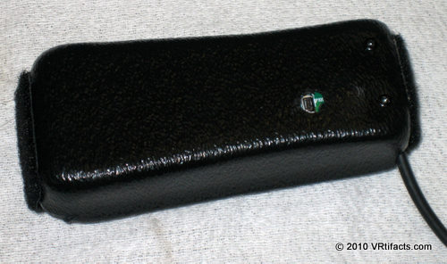
Top view. Vacuum formed case with peephole for channel switch.
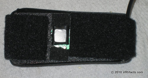
Silver cube sticking out of underside of case. Soft Velcro to attach to helmet.
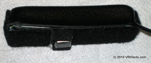
Finished tracker in enclosure – side/bottom view.
Step 11 – The Software
To Windows, the Gyration looks like a mouse. Most PC games handle mouse input directly and you won’t need any added drivers or software at all.
If you’re writing your own game, the code below provides a basic low level interface in raw mode to avoid window focus issues. You will still need to scale the coordinates so that one revolution of your head translates into one revolution inside the game space.
Call InitRawMouse() once at the beginning of your application to set up your tracker. Then call getRawMouse() whenever you need Yaw and Elevation
The code works just fine, but doesn’t do anything graceful with error conditions. Feel free to clean it up!
#if (_WIN32_WINNT < 0x0501)
 #undef _WIN32_WINNT
 #define _WIN32_WINNT 0x0501
 #endif
#include
 #include
RAWINPUTDEVICE Rid[1];
void InitRawMouse()
 {
 Rid[0].usUsagePage = 0x01;
 Rid[0].usUsage = 0x02;
 Rid[0].dwFlags = RIDEV_NOLEGACY; // adds HID mouse and ignores legacy messages
 Rid[0].hwndTarget = 0;
 if (RegisterRawInputDevices(Rid, 1, sizeof(Rid[0])) == FALSE) {
 //registration failed. Call GetLastError for the cause of the error
 }
 }
Int getRawMouse(LPARAM lParam, long *x, long *y)
 {
 UINT dwSize;
 RAWINPUT lpb;
GetRawInputData((HRAWINPUT)lParam, RID_INPUT, NULL, &dwSize,
 sizeof(RAWINPUTHEADER));
if (GetRawInputData((HRAWINPUT)lParam, RID_INPUT, &lpb, &dwSize,
 sizeof(RAWINPUTHEADER)) != dwSize )
 {
 return 0;
 }
if (lpb.header.dwType == RIM_TYPEMOUSE)
 {
 *x += lpb.data.mouse.lLastX;
 *y += lpb.data.mouse.lLastY;
 }
 return 0;
 }
/* Below is a sample of what your Windows event loop
 might look like. Look for a WM_INPUT message and
 pass it to the function OnInput() which calls
 getRawMouse() to update two static variables:
 Mouse_x and Mouse_y. Somewhere else in your
 program you probably want to scale Mouse_x
 and Mouse_y to be degrees, radians, or whatever
 form your program represents angles in.
 */
OnInput(LPARAM lparam)
 {
 getRawMouse(lparam, &Mouse_x, &Mouse_y);
 }
LONG FAR PASCAL
 WinVisProc(HWND hwnd, UINT msg, WPARAM wparam, LPARAM lparam)
 {
 switch (msg)
 {
 // Other messages
 case WM_INPUT: // WM_INPUT
 OnInput(lparam);
 break;
 }
 return (DefWindowProc(hwnd, msg, wparam, lparam));
 }
Step 12 – How to minimize tracker drift
I discovered three different ways to minimize the inherent drift in the Gyration sensors:
- Most of the drift resulted from dropped RF updates from the transmitter to the receiver. Even though the Gyration is spec’ed for 100 ft. of distance between the transmitter and receiver, I found that it started to drop updates at around 5-10 feet, or more. That’s not a problem as an air mouse which is a relative device, but is troublesome for an absolute orientation device such as a head tracker. My solution was to put the receiver at the end of a long USB extender cable so that it remained close to the tracker transmitter. In retrospect, given that I worked with the “wired” power configuration described above, I could have brought the USB cable up to the VR helmet and tracker transmitter, thus putting the receiver within inches of the transmitter and tapping power directly from the USB port.
- Some drift is induced by turning the tracker very rapidly; on the order of 200 deg. per second, or more. In practice, this is quite difficult to do while wearing a helmet. Neck injury will likely precede any drift.
- As a failsafe, I used an extra button on my hand controller which reset (in software) the mouse X/Y position to horizontal/forward. If the tracker drifted to far, the user could simply hold their head in a normal forward position and click the hand controller reset to get the tracker back in sync with their orientation.
